
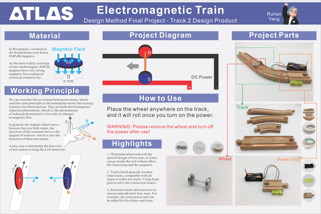
This is the final project for the Design Methods class. Students are required to choose a material, do a research or design a product. I chose the product track, and using magnets as my material, designed this electromagnetic train.
Material
In this project, I worked on the Neodymium-iron-boron (NdFeB) magnets. As the most widely used type of rare-earth magnet, NdFeB magnets have very strong magnetic force and good electrical conductivity.

Working Principle
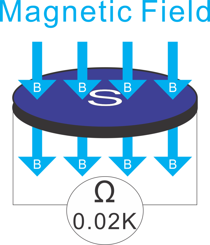
We can consider this as a linear homopolar motor, which used the same principle as the homopolar motor, but turning rotation into linear motion. They are both electromagnetic induction phenomena, which is, the phenomenon of induced electromotive force due to changes in magnetic flux.


In general, the magnet wheels move because they are both rotate, the direction of the resultant force is the tangent of rotation, which is also the direction of their movement.
A easy way to determine the direction of movement is using the Left-hand rule.

Project Parts
Wheel
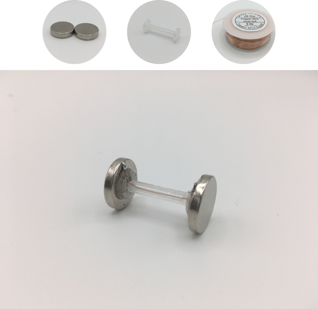
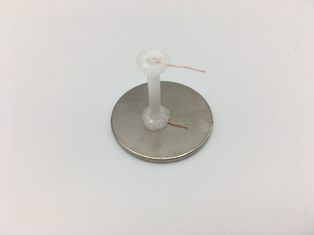
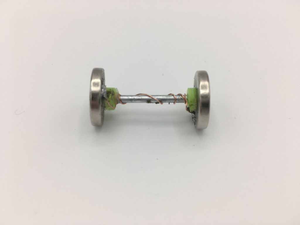
The design of the wheel rod Solved the problem of connecting the magnet to the wire. I originally planned to use an iron rod and solder it directly to the magnet, but the high temperature will make the magnet lose magnetism. Later I used strong glue to glue iron rods to the magnets, but then they would not be able to conduct electricity. On my prototype, I used iron rods and wound copper wires outside. In the final design, I designed a special wheel rod to place the copper wire inside.
The wheel is built with two round magnets, a 3D printed wheel rod, and copper wire. While assembling, the copper wire goes thought the wheel rod, stops in the grooves on both sides. Then connect the wheel rod to the magnet with hot glue, and finally weld the copper wire onto the magnet.
Track
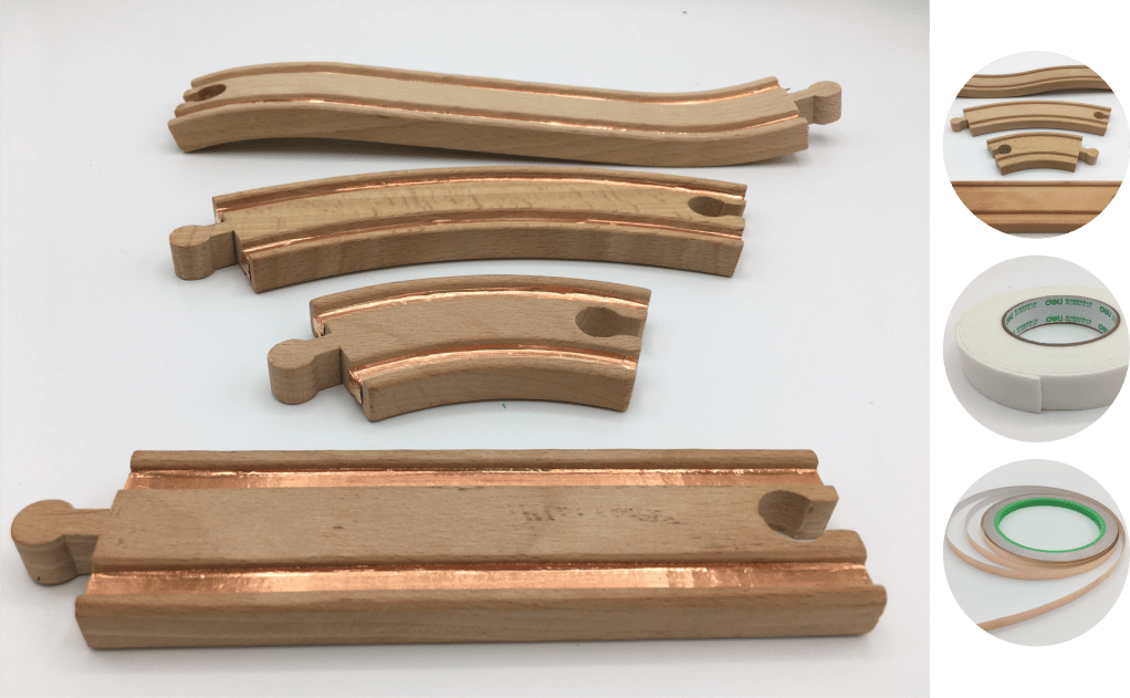
Tracks build upon the wooden train tracks, compatible with all major wooden toy trains. You can easily make the track by adding the copper tape into the groove of the wooden track. For better connection between the tracks, I added foam tape at the beginning of the tracks.
Power Unit
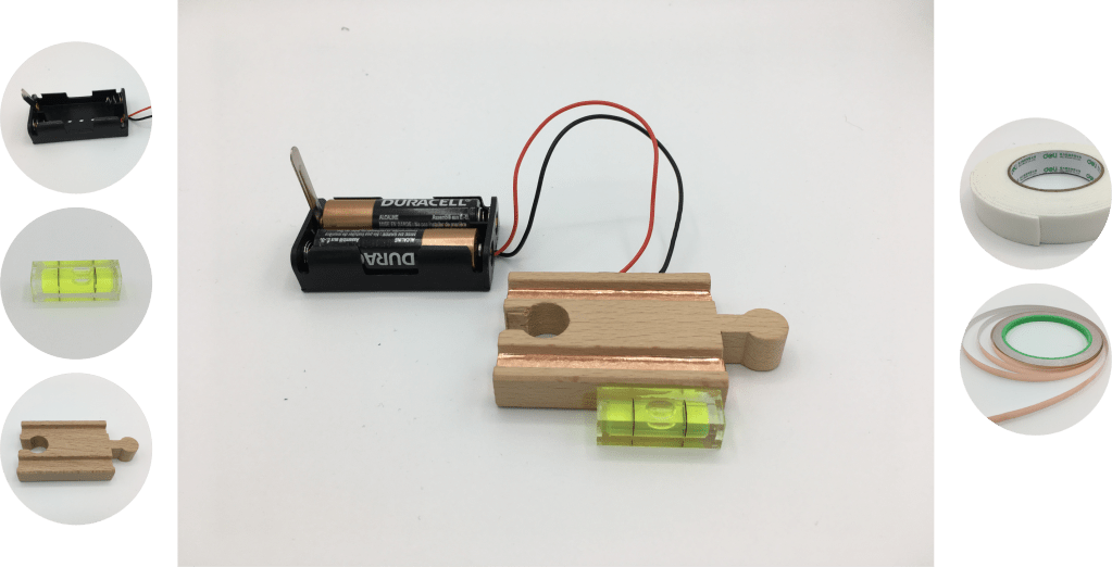
For the power unit, I attached the copper tape on the track from the bottom of the track to the side, and soldered the battery box to it. I also glued the bubble level on the side of it, which tells the user if they are laying the track horizontally.
Poster
Future Work
Thanks to Clement and Peter for their help and suggestions, I will replace the power unit with a hand crank DC power generator. We have tested the work of existing tracks and wheels, and the test results theoretically support this upgrade. I will continue to update on this page, and you are welcome to follow my Instagram to watch related videos and photos.
